Deep Dive - Passive Design & Its Process
Sustainability is the capacity to maintain resources for current and future use. The World Green Building Council states that the construction industry is the largest consumer of natural resources and raw materials, and produces an estimated 39% of the world's carbon emissions. Sustainability hinges on efficient resource usage by construction experts. To save energy, water, materials, and Indoor/Outdoor Environment, we will be concentrating on three stages of the building process: Design, Construction, and Operation.

Fig. 1. Different Phases for integration of Sustainability
Which people will be taking part in this process? This is a collaborative effort, which requires the participation of various fields such as Architecture, Civil Engineering, Electrical Engineering, Mechanical Engineering, and Plumbing. Each group must work together towards a shared purpose of creating a successful design.
The first step in creating a sustainable building is obtaining the client's commitment. Many people nowadays are conscious of their environmental impact and thus, they wish their buildings to be more efficient than others.
A significant and initial field in process of achieving sustainability is Architecture. It is important to design components such as it incorporates the strategies in the Fig 2. In this article, we will be having a deep dive into the Passive Design Process and examining its significance.
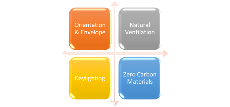
Fig. 2. Fundamental Sustainable Strategies of Architecture
The essential elements of self-sustaining structures are being explored in architecture. The most significant outcome of this endeavor is the introduction of Natural ventilation, which will replace the existing Mechanical Ventilation that is a notable consumer of energy (Fig 3).
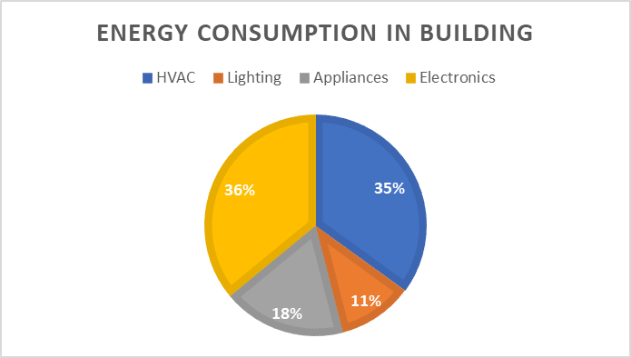
Fig. 3. Energy Consumption in Buildings – Source: US DOE
Natural Ventilation:
Natural ventilation is a type of ventilation that does not require energy to work, thus it is also known as passive ventilation. It can perform various tasks within a building, such as providing fresh air for air quality maintenance and ventilative cooling to reduce temperatures during hot weather. There are multiple designs of natural ventilation, from simple setups that are operated by manually opening windows, to more complex systems that are linked to a Building Energy Management System (BEMS) and mixed mode systems.
Using natural ventilation and ventilative cooling is attractive due to its potential for low energy usage and cost savings. Research demonstrated that in air-conditioned and mechanically ventilated structures, the carbon dioxide emissions from fans and pumps needed for moving conditioned air could be up to 50 percent of the emissions connected with space heating and cooling. Additionally, since air-conditioned buildings usually have a deep plan, the emissions from artificial lighting are considerable. A renewed examination of natural ventilation methods has been sparked by these facts, leading to an increased focus on more sophisticated natural ventilation systems.
Using natural ventilation has numerous advantages. Studies have revealed that people tend to prefer naturally ventilated buildings over those with mechanical or air-conditioned ventilation. In addition, the former had fewer sick building symptoms than the present. From a financial standpoint, constructing and maintaining buildings with natural ventilation is usually cheaper than those with more sophisticated mechanical systems. Maintenance is usually needed infrequently.
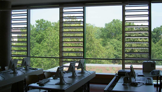
Fig. 4. Natural Ventilation for Offices
When creating successful naturally ventilated buildings, it is essential to incorporate natural ventilation into the overall building design during its development. Wind pressure fluctuates depending on the wind velocity, direction, and the building's location and shape in relation to its surroundings. Generally, the windward side of a building experiences positive wind pressure, while the leeward side experiences negative pressure.
When a temperature variation between interior and exterior spaces causes air to move, it will tend to flow vertically and along the easiest route. This is due to the variances in density and resulting pressure gradients. This phenomenon is referred to as the stack effect.
In recent years, varieties of natural ventilation systems have been developed for different purposes, some of which may even be supplemented by mechanical devices to further improve performance and control. However, these systems are always considered as the basic forms of ventilation strategies.
Single-sided ventilation
Single-sided ventilation typically serves single rooms and relies on vents on one side only of the enclosure. It is closely approximated in many multi-room buildings with opening windows on one side of the room and a closed internal door on the other side. There are two variants in single sided ventilation.
Single-sided ventilation with single opening:
This choice is not the most attractive option for ventilation, as it tends to have lower rates of ventilation and the air won't reach as far into the space. Generally speaking, the furthest distance for effective ventilation is about two times the floor to ceiling height, which is usually between 4 and 6 meters. In the summer, this option relies on wind turbulence to cause air to go in and out of the room. In the winter, if the single opening is tall enough, it is possible to achieve buoyancy-driven exchanges due to the higher temperature difference.
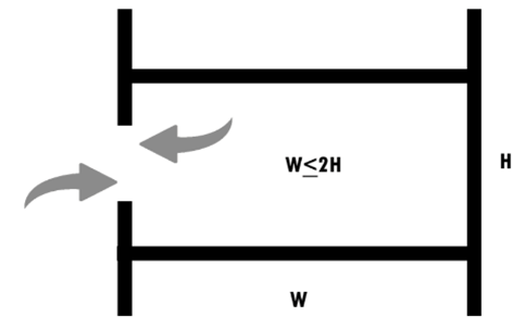
Fig. 5. Section of Single-sided ventilation with single opening
Single-sided ventilation with double opening:
The power of stack effects in this situation is amplified. The flow generated in the stack effect is determined by the vertical distance between openings and also by the difference between internal and external temperatures. Additionally, wind-driven ventilation is improved due to the increased likelihood of pressure differences between the two openings. To avoid cold air entering from the lower openings in winter, careful consideration should be given to where the inlets are placed in the room. Generally, the maximum depth for efficient ventilation is roughly two and a half times the height from the floor to the ceiling (7m to 8m).

Fig. 6. Section of Single-sided ventilation with double opening
Cross-ventilation:
Cross-ventilation is caused by wind-induced pressure differences that cause an inward force on windward surfaces and an outward force on leeward surfaces. For effective ventilation, the floor depth in the direction of airflow should be limited. As a general guideline, the maximum depth is five times the floor to ceiling height, which is usually around 15m. This requires the building to have a narrow plan depth, which is typically accomplished by having linear or open courtyard form.
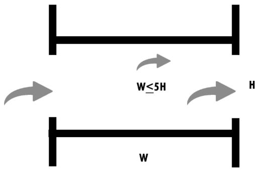
Fig. 7. Cross-Ventilation
Figure 6 provides an example of a wind-powered ventilation system with roof-mounted ventilators. It includes vertical sections with a higher pressure on the side facing the wind, allowing air to enter the space, and a lower pressure on the opposite side, which helps expel the air. Additionally, this type of natural ventilation system is usually composed of louvered terminals, a base, and adjustable dampers, which can be adjusted manually or by an automated control system.
Buildings that are particularly suited to roof-mounted ventilation include educational buildings, libraries, and health and community centers all of which require low operational and maintenance costs.
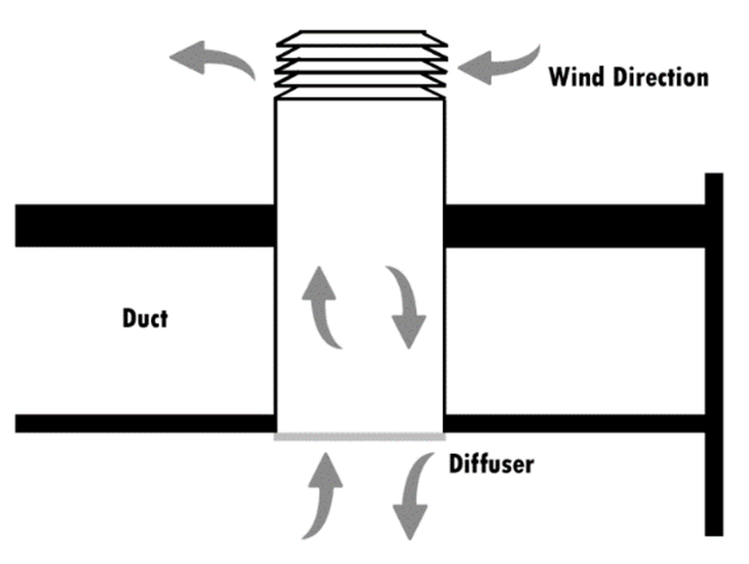
Fig. 8. Flow around and inside of a square roof-mounted ventilator
Stack ventilation:
Designers are finding ways to make the floor plans of their buildings deeper than usual by using stack ventilation. This kind of ventilation involves either specially constructed vertical ducts (also known as stacks, chimneys, or other similar terms) or a vertical space like an atrium. The airflow is produced by buoyancy, which is powered by differences in density between the indoor and outdoor air. Cooler, more dense air is drawn inside the building from low-level vents, while warmer, less dense air is expelled from higher level vents. Air within the building is always cooler than the air outside, and if the temperature difference is great enough, the airflow will reverse its direction.
The indoor air temperature is usually higher than the outdoor temperature, causing the air inside the building to rise. This creates a negative pressure at the bottom and a positive pressure at the top. To ensure natural ventilation, the temperature of the atrium or solar chimney should be kept high. But if the atrium is connected to other areas, it could make the occupied levels too hot. To prevent this, solar gains can be blocked using the components of the structure or solar baffles.
The roof vents must be placed in a space that is subject to lower pressure than the wind-induced pressure. To achieve this, one of the following design strategies from CIBSE should be utilized: forming the roof profile in a way that the outlet is in an area of negative pressure for all wind directions, incorporating an automated multi-vent system that will open and close outlets to guarantee that the exposed ones are always in a negative pressure zone, or employing a single vent system that is able to turn in the opposite direction of the wind.
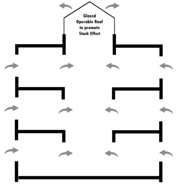
Fig. 9. Atrium Stack Ventilation
Mechanically assisted ventilation:
Physical mixed-mode strategies, as outlined by CIBSE, can be categorized into three groups: contingency design, complementary design, and zoned design. Contingency design is typically used in naturally ventilated buildings where mechanical ventilation or cooling can be added or removed if necessary. Complementary design is when both natural and mechanical ventilation systems are present and designed to work together without clashes or inefficiencies. Zoned design is when different ventilation strategies are used in different areas of the building. In the case of complementary systems, operational strategies are divided into two categories. Concurrent operation is an essential efficient mechanical ventilation system operates in parallel with natural ventilation systems. Changeover operation is both natural and mechanical ventilation systems are both options that can be used depending on the circumstances. For instance, seasonal changeover (which can include winter, summer, and mid-season modes), assisted night ventilation, supplemental cooling (when mechanical refrigeration is necessary due to a lack of natural cooling options), and local changeover (when a window is opened, the mechanical cooling is automatically turned off) are all possibilities. These systems do not necessarily need to be used at the same time.
Integration of strategies:
The above outlined strategies are regularly used in combination in a structure to meet various ventilation needs. For instance, a single-sided ventilation with a double entrance could be implemented in smaller areas (room A). Nevertheless, a local stack ventilation system could be employed to ensure adequate ventilation in deeper parts (room B). Moreover, in order to regulate the incoming air and to provide more control over air circulation throughout the building, an in-slab fresh air distribution system may be chosen (room C). This type of fresh air distribution is similar to the displacement ventilation, most commonly implemented mechanically, and similarly relies on thermal plumes generated by equipment and by occupants to assist airflow and improve air quality in the ventilated enclosure. At last, for larger occupant-density spaces (room D), the cooling capacity of natural ventilation may not be enough to avoid overheating, and an additional mechanically assisted strategy might be needed.
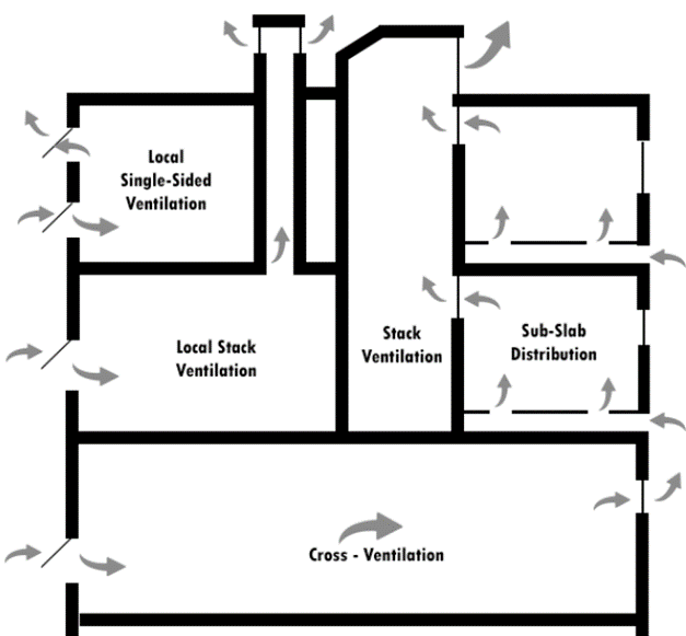
Fig. 10. Integration of Ventilation Strategies
Design performance evaluation
To make sure the natural ventilation system functions properly, it is essential to follow sound engineering practices. This includes assessing the plan in different weather and thermal conditions, and as certaining situations where the objectives could not be achieved. Depending on the design's needs, the natural ventilation systems test must take into account energy use (and the related carbon dioxide emission), air movement (caused by wind, pressure contrasts and mechanical forces in the instance of mixed-mode ventilation systems), and air pollutant dispersion. The connection between the exterior and interior of a building, and the atmosphere around it, is intricate and difficult to address with a single approach. As a result, a broad selection of assessment instruments have been created.
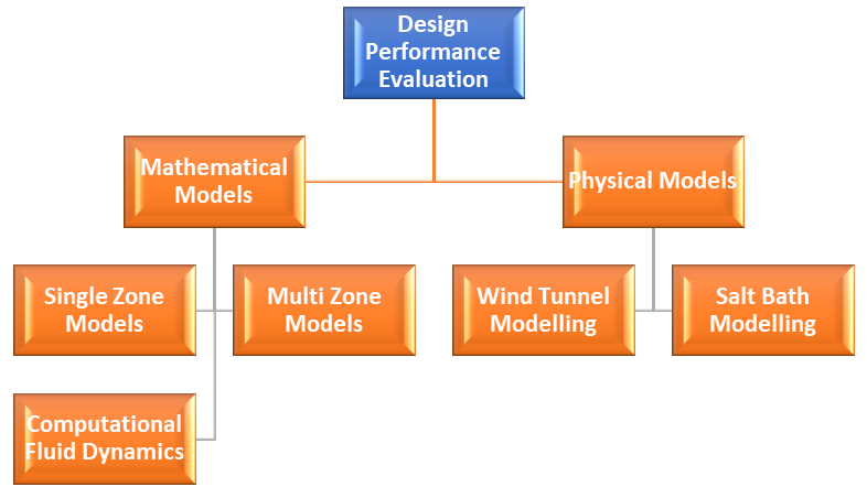
Fig.11. Methods of Design Performance Evaluation
Control systems:
Keeping natural ventilation systems operating at optimal rates is a major challenge in their development. Wind and buoyancy forces cannot be easily regulated, making control difficult. This lack of control can lead to problems such as inadequate air circulation causing thermal discomfort, or poor air quality due to under-ventilation, or excessive heat loss due to over-ventilation. The easiest way to implement an automated system for managing a naturally ventilated structure is to install one or more temperature sensors in the space to obtain an average reading. This approach is suitable for many scenarios. In summertime, dampers usually are configured to start opening at 16°C and open further by 20% for each degree of internal room temperature rise. For winter, the temperature settings can be adjusted to avoid energy loss. For places with a lot of people, like classrooms or meeting rooms, CO2 sensors may be installed together with temperature sensors. The best spot to put the CO2 detector is likely to be around the heads of those seated in the room. To supplement the temperature and CO2 sensors, an automated control system for a naturally ventilated building may also include room occupancy, humidity, and rain sensing, outside air temperature, wind speed and wind direction sensors. Normally, these parameters can be recorded, but are usually used for performance assessment purposes.
Case Study: Senedd Cymru Welsh Parliament
Introduction:
The Senedd is a building located in the waterfront area of Cardiff Bay, Wales. The design for the three-story structure was created in by Richard Rogers and Partners, architects and engineers. It was constructed with natural ventilation in mind, with a roof cowl aiding in ventilation and allowing for maximum daylight to enter the building. The public can access the main entrance, café, and seating areas, while the chamber is reserved for the 60 assembly members.
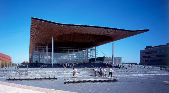
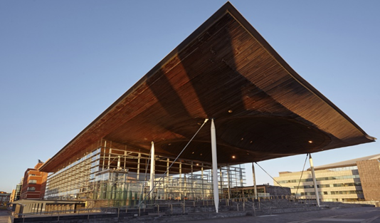
Fig. 12.a,b Views of Senedd
Natural Ventilation:
Natural ventilation is the most common type of ventilation used in buildings. All public areas are ventilated naturally using the windows in the glazed facades. Thermal mass materials such as concrete and slate are utilized and helping to regulate the internal temperature. The debating chamber and committee rooms have an air-conditioning system as a backup in cases of high heat or more stringent climate control. The air is brought in through intakes in the floor and is expelled through the windows in the committee rooms or through the chamber's roof funnel.
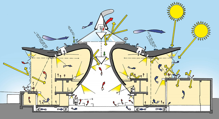
Fig. 13. Section highlighting natural ventilation of Senedd
The cowl at the peak of the chamber is 6m tall and can rotate depending on the wind direction; this arrangement creates a vacuum on the side away from the wind, where vents are placed to expel hot air from inside the building. This helps to reduce the need to cool the area artificially and thereby reduce energy costs.
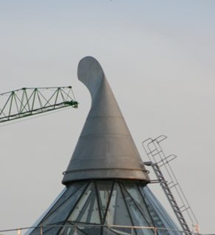
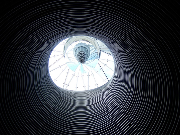
Fig. 14.a,b Interior and Exterior view of Cowl
Daylight:
Daylight has an essential role in the sustainability of Senedd. When planning this project, scientists conducted thorough research to make sure they could maximize the amount of sunlight and natural light that could enter the building, based on the time of year and time of day. The internal parts of the building get illuminated by a combination of artificial and natural light. The main source of natural light is a conical mirror situated at the top of the structure, which reflects it inside. The walls and roof of the building are glazed, to ensure high levels of daylight penetration.

Fig. 15. Section highlighting daylight of Senedd
Cooling strategy:
The Senedd contains an array of environmental regulations. In the common areas, the minimum ventilation is regulated, but the meeting rooms and debating hall have stricter control. This is where the backup air conditioning is located. The cooling system uses ground earth heat exchangers, which involve the placement of 27 boreholes in the ground and the use of ground source heat pumps. The pipes underneath the slate floor transport cool water and extract the heat from the building. The heat generated is then transferred to the ground, resulting in a reduction in cooling requirements. Additionally, this system can be used as an under-floor heating system during the winter. The benefits of this system are twofold: it reduces the size of traditional boilers and chillers, and it is more efficient, resulting in considerable energy savings. The engineers are confident that the building will consume no more than half of the energy a traditional building would in the same location.
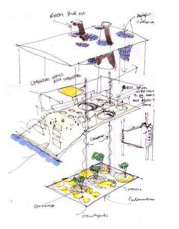
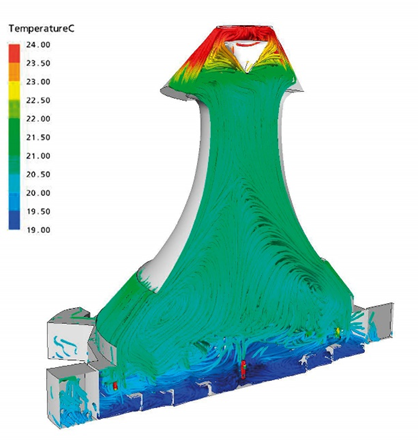
Fig. 16.a,b cooling strategies and measures of Senedd
Case Study: National Trust Headquarters – Heelis Building:
Introduction:
The Heelis Building is the National Trust's new home, situated on the grounds of the Great Western Railway Works in Swindon. It is a two-storey structure with a total area of 7000m2, primarily used as offices, along with a shop, a cafe, and a recruitment area. Fielden Clegg Bradley, the architects, made sustainability their priority, and so they set high standards in order to achieve this. This is one of the few large office buildings that rely mainly on daylight and natural ventilation for cooling, rather than mechanical systems.
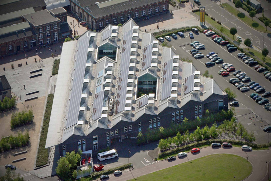
Fig.17 View of Heelis Building
Natural Ventilation:
The design of the structure is based on a natural ventilation system. Its plan is arranged so the facade is in the south direction and the double-pitched roof faces north-south. This design creates an east-west axis, with two primary courtyards located in the middle, which act as a ventilation system to ensure proper air circulation in the innermost parts of the building. Windows and large ventilation panels on the south wall are set at a high level to allow air to enter the building. These panels are regulated automatically. Windows can all be opened by hand, giving those inside the ability to adjust the environment. Special vents, known as 'snouts', are situated in the roof to exhaust air. In particularly hot weather, the outlets are reinforced with mechanical aids. Two diagrams demonstrate this entire ventilation approach in fig. This achievement of Natural Ventilation is by stack effect, which is further improved by the outside wind.
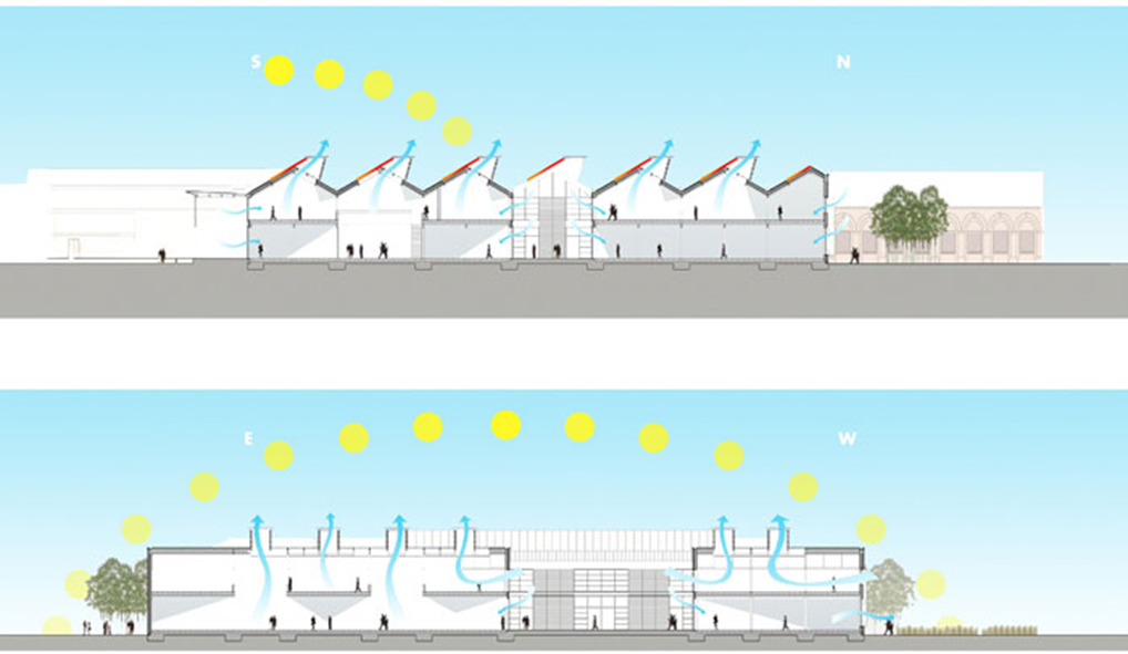
Fig.18 Section of Heelis Building
Daylight:
The Heelis Building utilizes natural light for a majority of its illumination. Its roof is equipped with glazed components that let in sunlight to the ground level. The south side of the roof has photovoltaic installments, which provide roughly 15 percent of the total electricity usage of the building. To let in even more light, there are gaps on the first floor that allow the daylight to reach the bottom floor. The majority of the inside areas have a daylight factor that is higher than 5 percent. On the first floor, lights are hardly needed, but the bottom floor has a few places under the mezzanines that often have illumination. The two courtyards also contribute to more natural light entering the building.
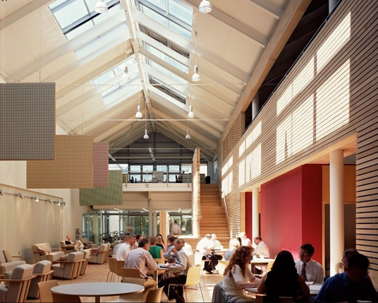
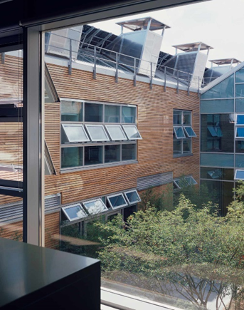
Fig.19.a,b Daylight in Heelis Building
Cooling strategy:
The entire strategy for cooling relies on night ventilation. The 442mm thick walls, made of concrete block work and external brickwork, together with the roof, which is made of 80mm thick exposed precast concrete panels, have very high insulation values and high thermal resistances. In this way, they comprise the thermal mass of the building, which absorbs the internal heat gains during the day and purges them during the night. However, in spaces with high internal heat gains and stricter internal conditions, such as board rooms and computer rooms, mechanical cooling is needed. The usage of local fan coils in a mixed-mode system, which utilize water cooled by a refrigerant without Ozone Depleting Potential, demonstrate the significance of passive design process.
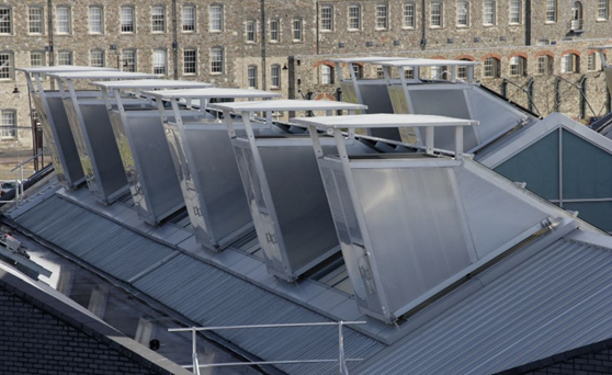
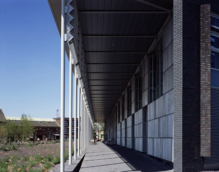
Fig.20.a,b Detail of Snouts and Shades
Conclusion:
We can see from these examples how significant passive design is in terms of its effects. It will play a role in all stages of design, from mixed ventilation to mechanical ventilation and beyond. As designers, we can make a difference in the designing process by using sustainable passive design strategies like natural ventilation and daylighting can save upto 40% of the Energy consumption of building in the design development itself. This dedication from designers will have a big impact on the building industry, allowing us to progress towards a sustainable future.
Bibliography:
McMullan, R Environmental Science in Building, Palgrave.
Haliday S. Sustainable construction. Routledge.
Roaf, S. Adapting buildings and cities for climate change: a 21st century survival guide
Santamouris, M. & Mumovic, D. A Handbook of Sustainable Building Design and Engineering
About the Author:
Kishore Kumar K, Sustainability Projects Coordinator, currently working in Saudi Arabia. Kishore Kumar is an architect with Accredited Professional by green building rating systems like Envision, WELL, GSAS, LEED in Building Design and Construction, Interior Design and Construction, Operation and Maintenance. He remains motivated and engaged by learning new trends and challenging things. He is driven by his passion for sustainability, which leads him in pursuit of a sustainable and regenerative future for the benefit of society. He always believe “Thirst for knowledge is the key for success”
LinkedIn: https://www.linkedin.com/in/kishorekumark/
Picture Credits
|
Figure |
Credits |
|
4 |
https://shorturl.at/agqXZ |
|
12.a |
https://shorturl.at/vQU02 |
|
12.b |
https://shorturl.at/artHX |
|
13 |
https://shorturl.at/eflB6 |
|
14.a |
https://shorturl.at/prFHZ |
|
14.b |
https://shorturl.at/cCLV1 |
|
15 |
https://shorturl.at/nvwxI |
|
16.a |
https://shorturl.at/lCMQ2 |
|
16.b |
https://shorturl.at/aeHIQ |
|
17 |
https://shorturl.at/ilyY8 |
|
18 |
https://shorturl.at/kAOS6 |
|
19.a |
https://shorturl.at/sxKLP |
|
19.b |
https://shorturl.at/juAKQ |
|
20.a |
https://shorturl.at/uyCJ2 |
|
20.b |
https://shorturl.at/anrF8 |

